Cranktrain Simulation
DIGITAL ENGINEERING AND EVALUATION
Cranktrain Design Process
The crankshaft is the central component in an internal combustion engine. When designing and optimizing a crankshaft, vibration and deformation angles, main bearing forces and safety factors in each crank web must remain within specified limits for all operating conditions of the engine. Depending on the different simulation tasks, there are different ways to build a crankshaft model. It is either possible to obtain an initial impression of the crankshaft dynamics and the loads in a very short time or to take a close look at the resulting safety factors under the influence of various boundary conditions.


All-in-one solution
The 3D crankshaft geometry with its main dimensions is built up from individual webs, which are generated in the integrated parametric crankshaft design tool and automatically meshed (surface mesh). Alternatively, externally generated surface meshes can also be easily loaded for each web.
At the touch of a button, the structural dynamic properties of the individual webs are calculated on the basis of the boundary element method (BEM) and automatically converted into a 3D -flexible MBS model and a 1D torsional model of the crankshaft
Integrated CAE tool chain
Here, the design is carried out in an external CAD system. In an intermediate step, the creation of the MBS model requires the CAD geometry to be meshed and a CMS reduction to be carried out with an appropriate FE program (e.g. Nastran, Permas, Abaqus, Ansys, etc.). The crankshaft is then represented as a flexible structure in the multi-body system

Cranktrain design & Virtual validation
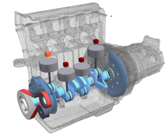
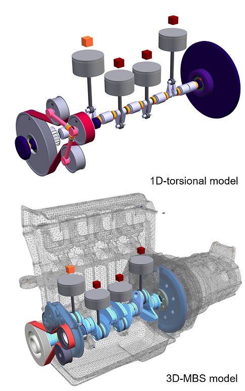
After the final crankshaft-design was defined, a MBS model of the complete engine was assembled to predict vibration- and deformation-angles and all other calculation results in the simulation. This MBS model consists of the typical engine-components:
1D-torsional model:
-
crankshaft
-
con-rod and piston
-
torsional vibration damper (TVD)
-
flywheel
-
FEAD
3D-MBS model:
-
crankshaft
-
torisonal vibration damper (TVD)
-
flywheel
-
FEAD
-
main- and con-rod-bearings (HD or EHL)
-
environmental stiffness or flexible crank housing
Journal Bearing
Elastohydrodynamic Lubrication (EHL)
If, in addition to the main bearing forces, the bearing moments, edge pressure, minimum film thickness and the oil supply condition are also to be taken into account when designing the crankshaft, an EHL bearing calculation is required. The EHL bearing element in SIMDRIVE 3D provides a fast, high-performance solution for use even in a transient full-load run-up.


Tasks in Cranktrain Design
1. Analyses of already designed crankshafts with different boundary conditions:
-
changes in the peak cylinder pressures
-
influence of different flywheel-inertias on safety factors
2. Evaluation of smaller changes to an existing crankshaft while main dimensions stay the same:
-
changing properties of the TVD
-
changing size or number of counterweights
-
comparison of different firing orders, which make changes in the crankshaft-layout necessary
3. Defining the main crankshaft-dimensions at the beginning of a new engine project:
-
diameter of the main- and con-rod bearing-pins
-
radius between these pins and the crank