PSM Dynamics Simulation
DIGITAL ENGINEERING AND EVALUATION
The different models of electrical machines within the controller environment are designed to work with standard parameters often directly provided by the supplier.
Additionally we provide tools to parametrize electrical machines directly in SIMDRIVE3D.
Parameter identification
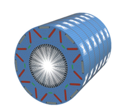
The E-Motor Designer element allows users to analyze machine drafts based on a parametric 2D cross-section and material properties
set up a magnetostatic finite element analysis within the MBS model frame.
-
Identify nonlinear parameter maps for the synchronous machine model as well as torque harmonics.
-
Compute current dependent 3D force maps for the excitation of flexible rotor and stator bodies through the Air-Gap Element.
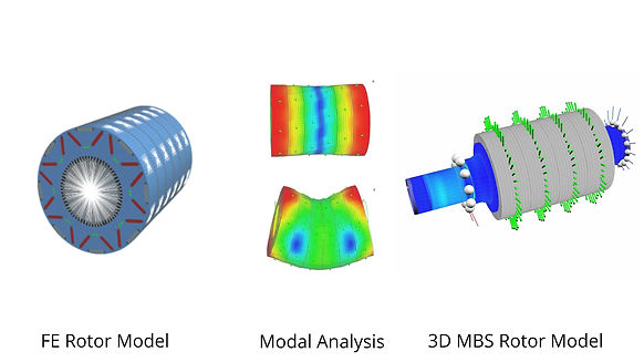
FE Model of the Rotor
A fully dimensioned 3D-FE model of the rotor assembly is automatically generated and written as an input deck for a CMS reduction based on the geometry defined in this element. After reduction with an external FE solver, e.g. Nastran, Permas, Abaqus, the rotor is available as a flexible body in the MBS simulation. The modal analysis is carried out in SIMDRIVE 3D.


Model variants
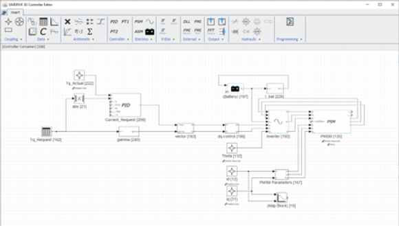
The Within the same MBS model, the generated data maps of the motor designer can be linked directly to the machine parameter inputs within the controller environment to build performance oriented models with closed loop controllers. This setup allows users to
-
Evaluate the defined motor geometry in combination with Inverter and battery models
-
Set up parameter studies to test varying system parameters and boundaries like the maximum power loss, the effective current limit or the SOC depended battery voltage
-
Compare the outcome of different model tasks within the result export tool